New lab power supply
Posted on So 18 Juni 2023 in Computer & Electronics
Electronic gadgets need power. And if the device in question doesn't come with a power supply or it's a repair job and you suspect that the PSU is part of the problem, then a lab power supply comes into play. I've had a Voltcraft PS405-pro power supply for ages and a Manson NSP2050 switching power supply is also hiding somewhere. Both are OK, but I felt the urge to treat myself to a new one that is properly programmable and offers remote control and a better user experience.
So I did some homework and found a variety of offers. These made it onto my shortlist:
- Rigol DP832 / DP832A
- Siglent SPD3303X / SPD3303X-E
- Owon ODP3033 / ODP3063
- UNI-T UDP3305S / UDP3305S-E
Siglent and Rigol fall into the "Respectable Chinese Vendors" category, while Owon is known more as el cheapo supplier (although I found some very positive reviews of the PSUs mentioned above). UNI-T's reputation seems to be mixed: Their multimeters are pretty popular but the community doesn't seem to like UNI-T as well as Rigol or Siglent. Nevertheless, after hours of studying data sheets, manuals and reviews, UNI-T's offerings appealed to me most:
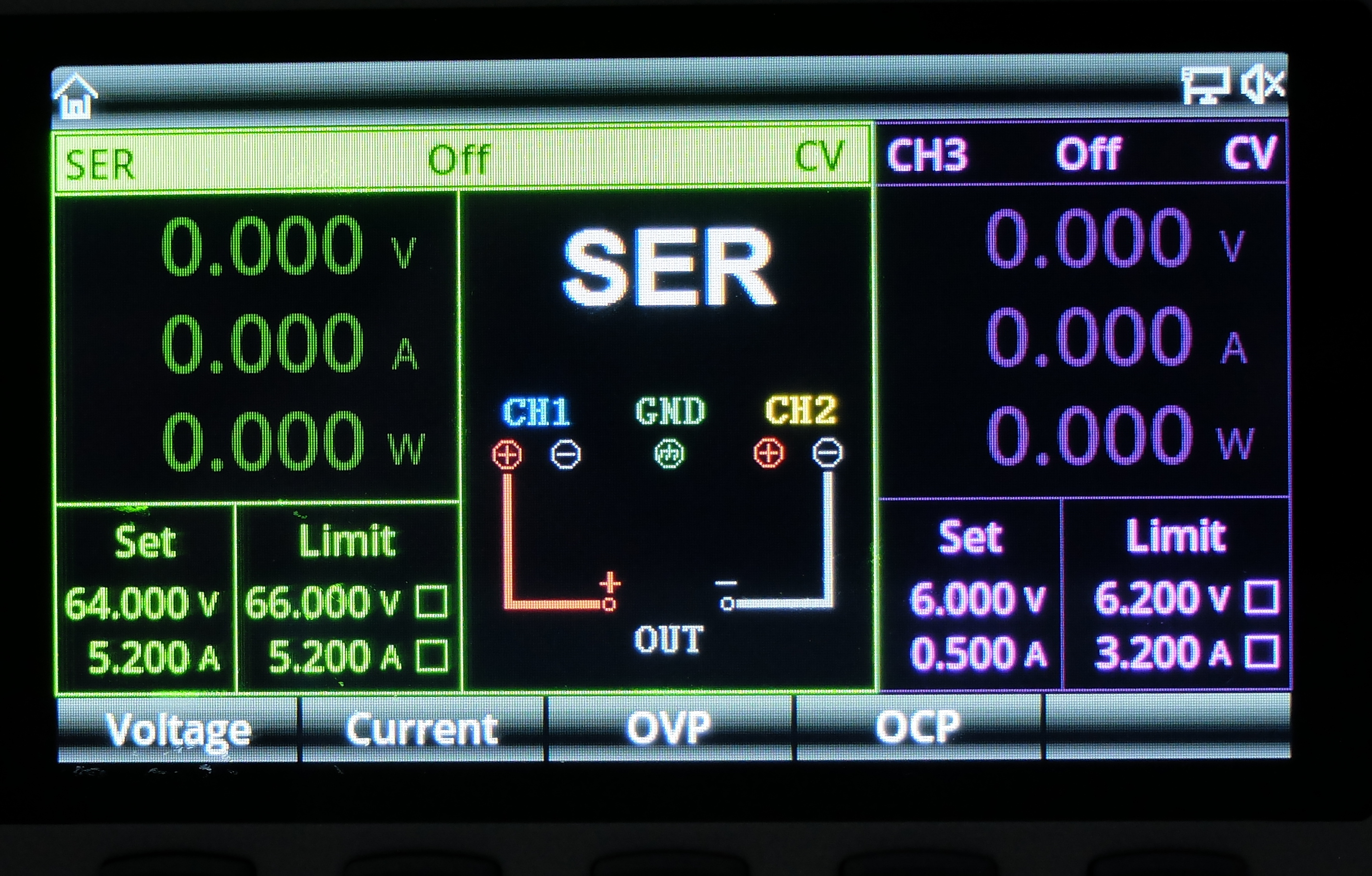
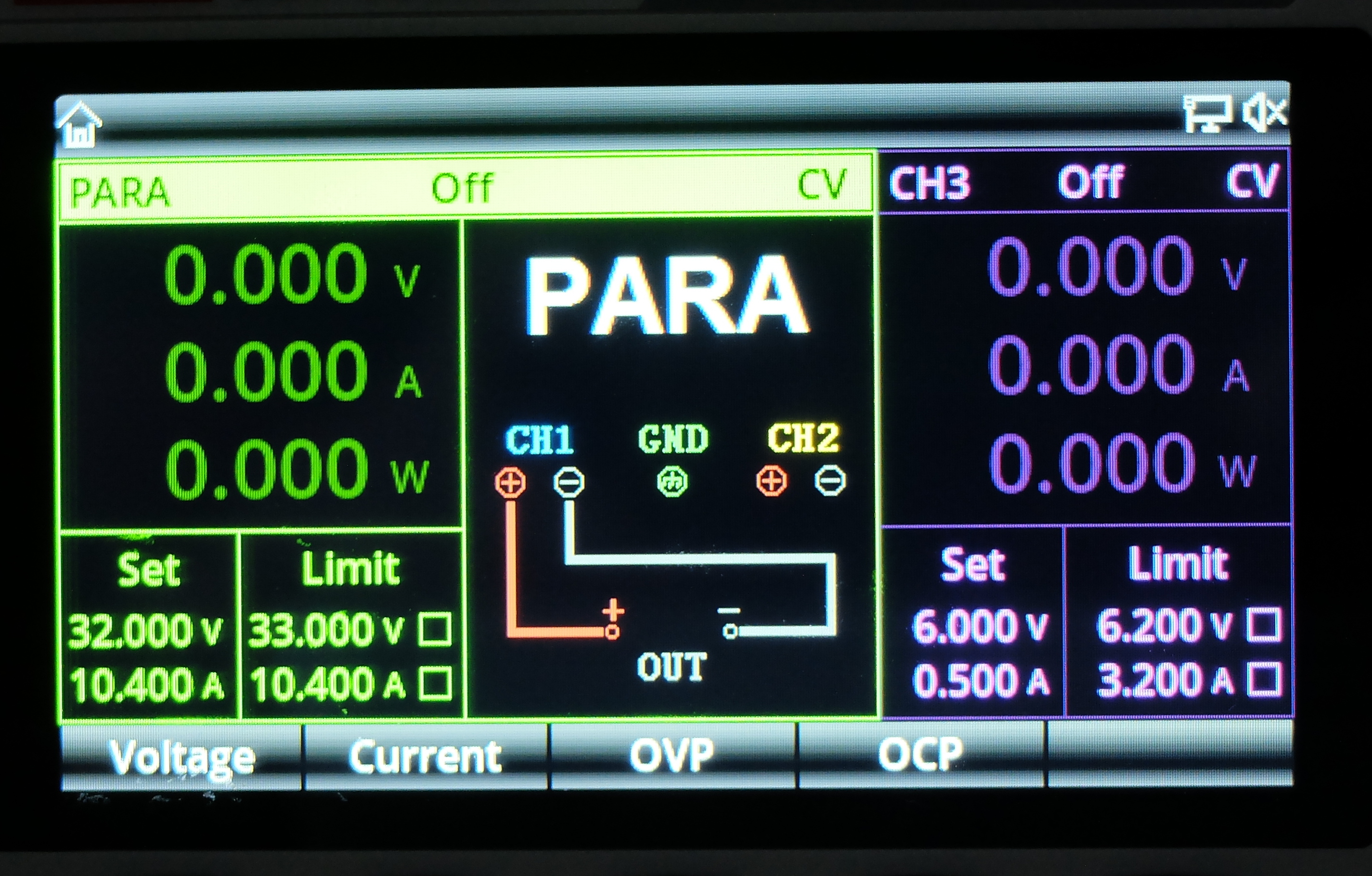
- Channels 1 and 2 offer 0-32V at 0-5A. They can be connected in series or parallel, easily to get more voltage or higher current.
- Channel 3 is mainly intended for the supply of digital circuits. You get 1.8V, 2.5V, 3.3V and 5V at the touch of a button, but you can set any value between 0 and 6.2V and you get up to 3A.
- "Channel 4" is pure marketing and doesn't really exist: It's a USB-A socket that supplies 5V at up to 2A.
- Large color display
- Number pad for entering values quickly
- Versatile programming
- 1 mV / 1 mA resolution (or 10 mV / 1mA for S-E model)
- Ethernet, USB, RS232 and a few digital pins
- SCPI
None of the competitors offer all of this:
- The Rigol is a lot less powerful and the numeric keypad is awkwardly arranged in a circle around the dial - I guess that's supposed to look cool...
- The Siglent has less power and no number pad at all. Ch3 is limited to a few fxed settings. Programming is also less flexible.
- The Owon has slightly more power and a number pad, but is less flexible in terms of programming, the channels are arranged in a weird order (3, 1, 2) and the display uses different colors for the channels than the color codes on the front (at least that's how it appears in the marketing pictures).
Nevertheless, I hesitated for quite a while, because there are almost no reviews about the UNI-T power supply out there. Part of that may be because it's fairly new to the market, but it would make me feel more comfortable knowing that people out there have given it a good look. For the contenders from Rigol or Siglent, there are plenty of reviews on YouTube and in various blogs – including hacks to upgrade the smaller/cheaper models for free. For the Uni-T, I could only find a single, short thread in the EEVblog forum that didn't have much information at the time. I had already considered jumping in at the deep end and order it without more information as user Self Bias posted his rather positive observations. So I ordered with more confidence.
It arrived two days later:


So let's give it some testing to see if that was a good decision or not.
User interface and build quality
The device makes a solid impression. The keys are made of rubber but have a clearly noticeable click to them. The knob clicks nicely and precisely. The display has glare, but that doesn't really bother me.
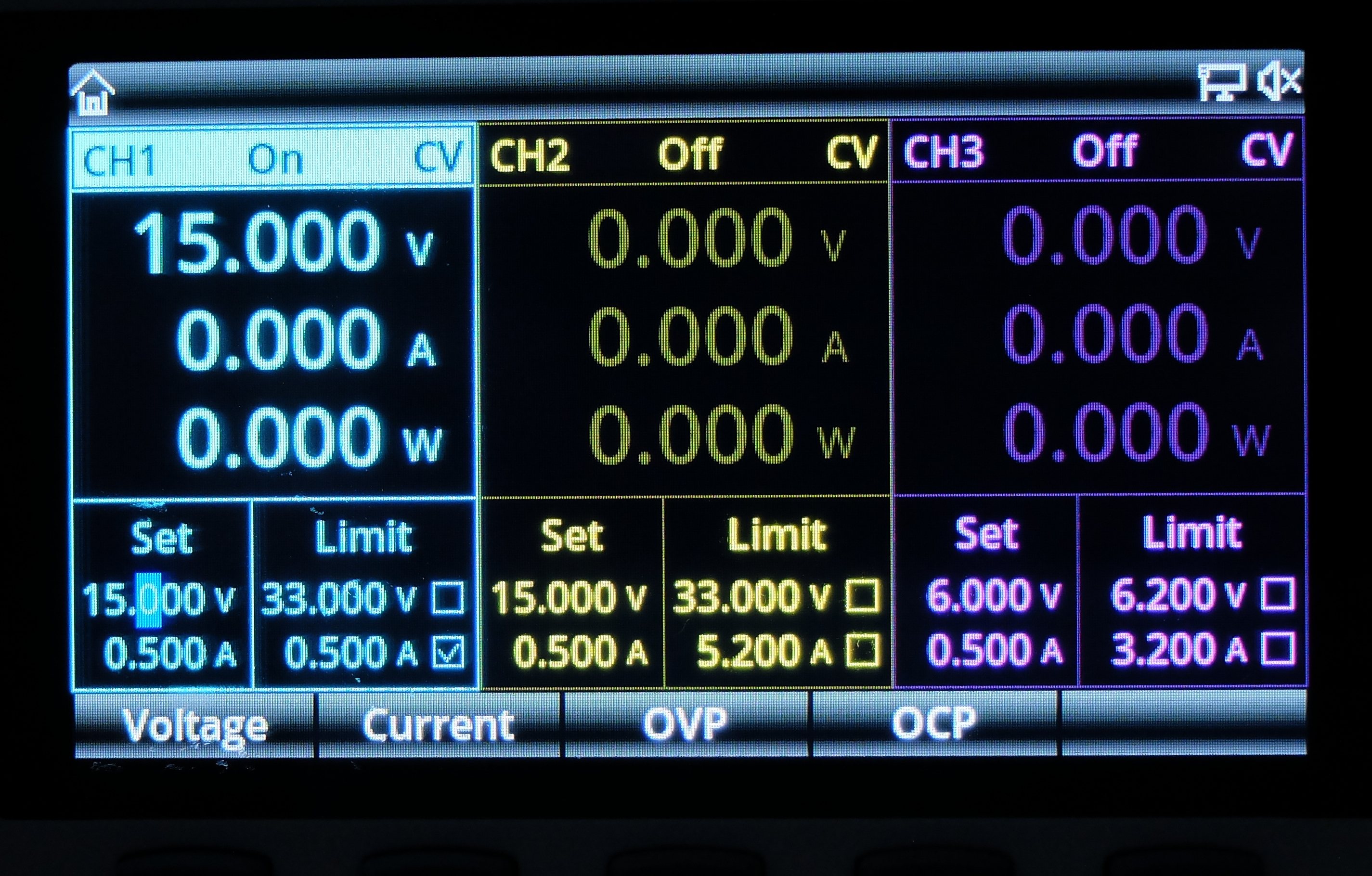
The binding posts have the standard spacing of 19mm (3/4") and the banana plugs of my test leads firmly fit into the sockets. The display shows all relevant data in a tidy fashion.
The various buttons and menus are mostly self-explanatory and apart from a small spelling mistake ("Templet" instead of "Template") I didn't really notice any Chinglish.
The display always indicates whether we are in constant voltage (CV) or constant current mode (CC). In addition, all three channels have an LED above the respective sockets, which lights up in green (CV) or red (CC), as is common on traditional power supplies. I think that's great, because it makes it so much easier to see when the current limitation takes effect on a channel.
When channels 1 and 2 are configured to be in parallel or in series, the display prominently shows a small picture of the appropriate wiring in the respective configuration. What appears to be missing is a classical tracking mode in which ch1 and ch2 are tied together and controlled jointly. You can kind of get that in serial mode if you use all four output sockets but the display will only show the added voltage and, of course, both voltages are identical in this mode. I guess a true tracking mode could be added in firmware so maybe there is hope to get that in the future.
Common voltages for digital circuits (1.8, 2.5, 3.3 and 5V) are quickly accessible as presets via a small button for channel 3. But you can still set any voltage you like in the range 0-6.2V. So it is a fully-fledged channel with current limitation, etc. – just with a lower maximum voltage/current.
What I really like is the ability to set voltages or currents via the number pad instead of fiddling with an encoder wheel. It's so much quicker and more convenient.
Here are some screen shots (looks much nicer in the real world than in the pictures):
All in all, I have to say that the power supply probably has one of the best user interfaces I've come across on a Chinese device, so far.
Fan Noise
After switching the device on, the fan whirrs quietly to itself.
Now let's put some load on it. So we set the power supply to 20V and the electronic load to 50W. After 10 minutes I switched off the load, but the power supply fan hardly seemed any louder. That was probably not enough load to really put stress on it.
So let's try harder:
- Connect Ch1 and Ch2 in parallel
- Set 32V on the power supply
- Add 200W load
- wait for 10 minutes
- Turn off the electronic load and check fan noise
Result: The fan on the electronic load roars. The power supply is still nice and quiet.
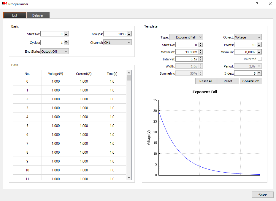
Programmability
You can program the power supply directly via the user interface. And that's surprisingly easy. The user interface shows a big table with 2048 rows and each row contains a set of parameters.
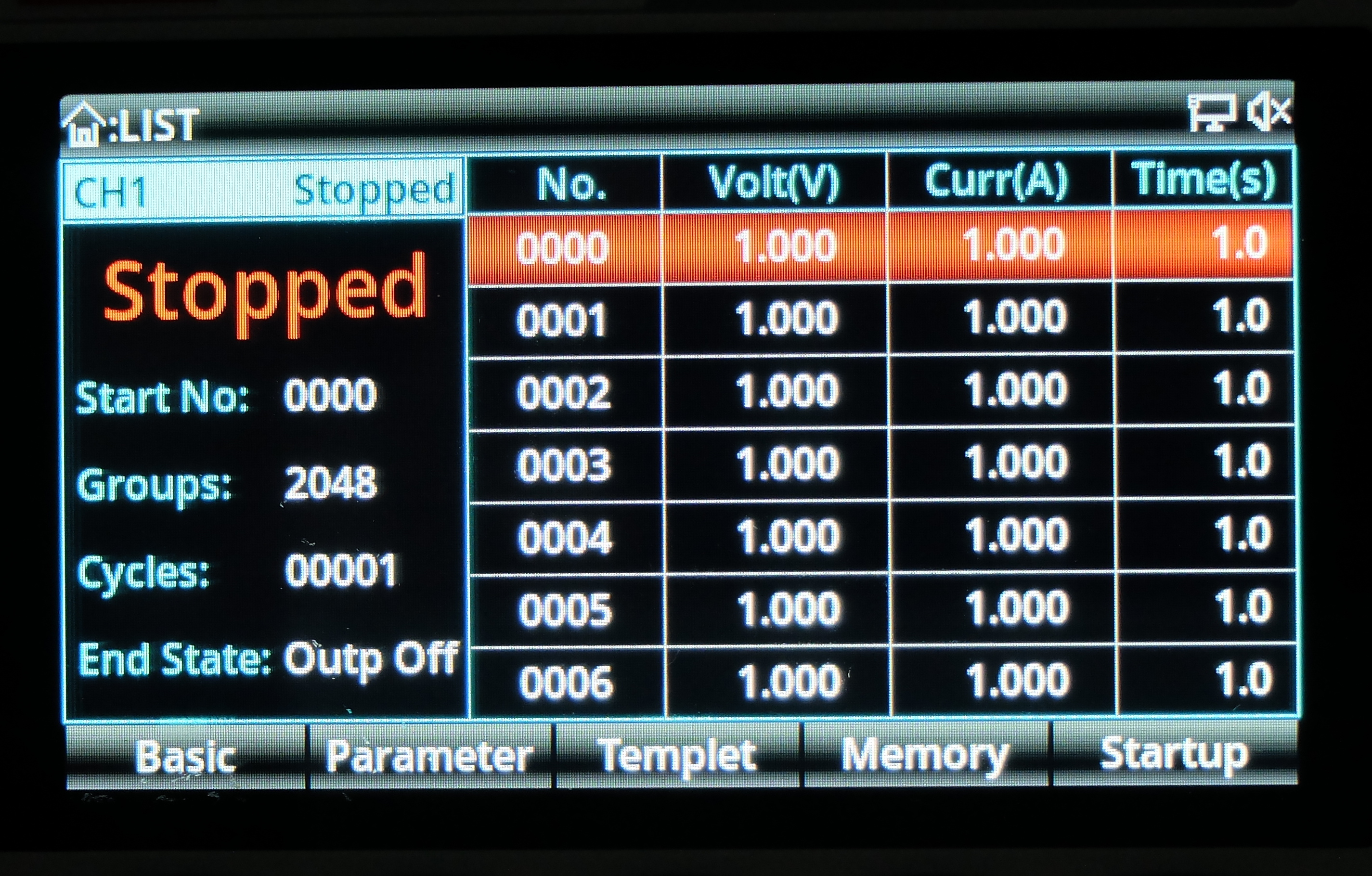
To run a sequence, you just tell the device where in the table to start and how many entries to go through.
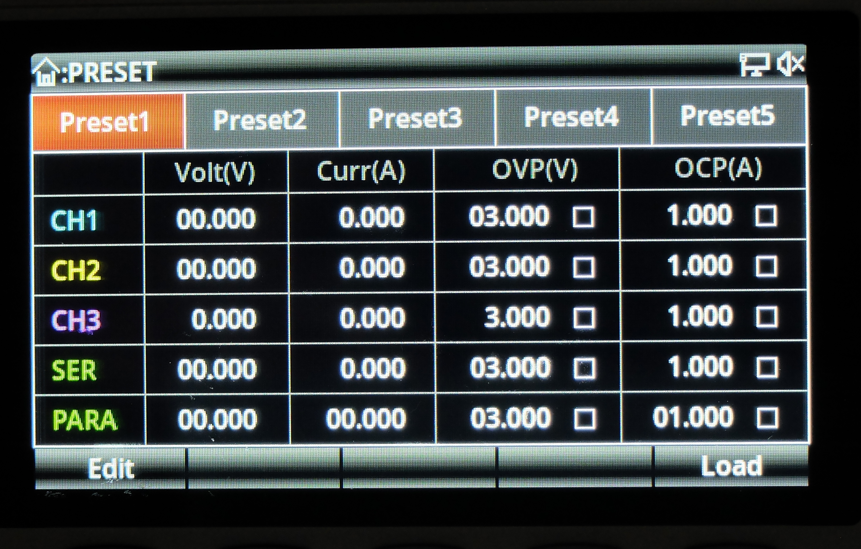
Finally, you can store five sets of presets: So if there are certain configurations that you need more often, just program the desired values for all channels in one of the presets. E.g. 12V on Ch1, 5V on Ch2 and 3.3V on Ch 3 – including settings for current limits etc.
Oh – and you can define actions that are to be taken under certain conditions – e.g. warning messages, beeps or turning off a channel upon certain events.
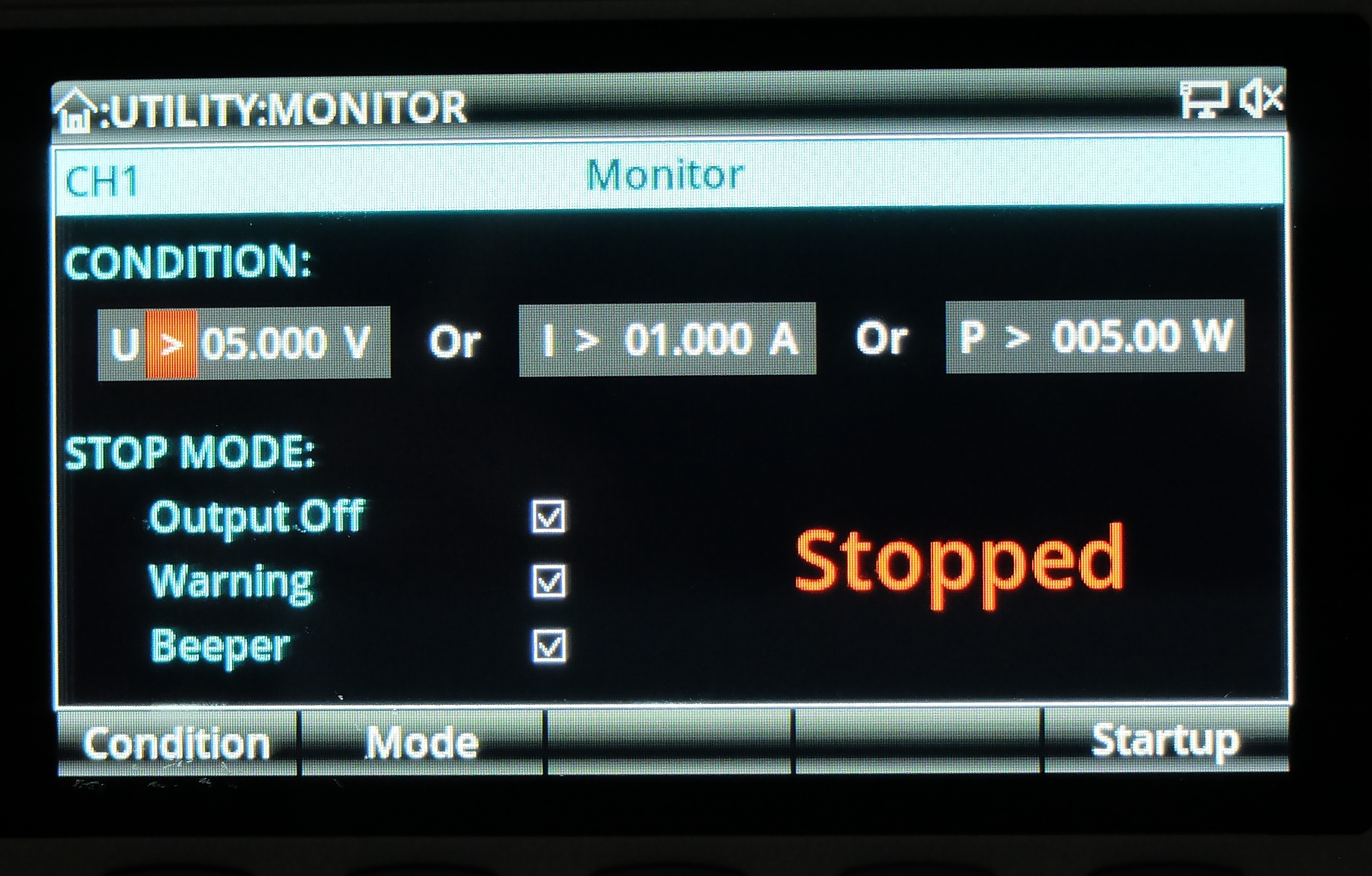
That may come in handy for getting notified when things go awry or to shut down the power at the end of a charging cycle.
Software
The software that comes with the instrument will only work on windows, of course. So I installed it on a virtual Windows machine for a quick look but didn't test in depth.
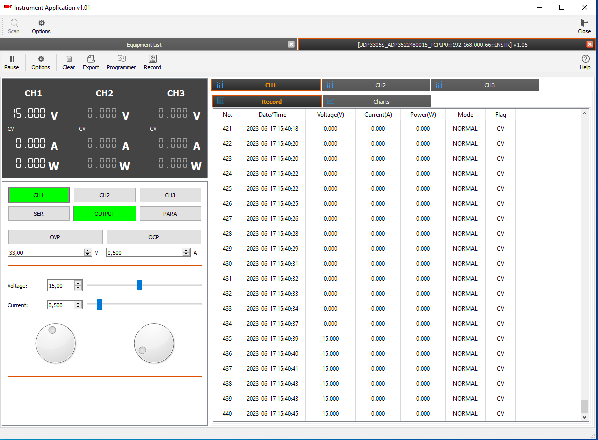
It seems to be decent, but the installation is very large and takes forever. It also seemed to me that the power supply reacts to the software rather sluggishly. But that that may be due to the overhead from the virtual windows.
Remote control
When you want to control more complex scenarios it's often easier to write a script than fiddle with vendor software. The device has three ports you can use to connect it to a computer: USB, RS232 and ethernet. All three will give you the capability to send SCPI commands. A programming (SCPI command) manual is available from the manufacturer's web site.
We already played with the Windows software above, but I prefer LINUX and would love to use Python for scripting. So I looked around and discovered PyVISA. That looks quite promising. So let's install it:
python -m venv .venv
source .venv/bin/activate
pip install pyvisa
pip install pyvisa-py
Now launch an interactive python session and have a look:
>>> import pyvisa
>>> rm = pyvisa.ResourceManager()
>>> rm.list_resources()
('ASRL/dev/ttyS1::INSTR', 'ASRL/dev/ttyS0::INSTR', 'TCPIP::192.168.0.65::INSTR', 'TCPIP::192.168.0.67::INSTR')
>>> psu = rm.open_resource('TCPIP::192.168.0.66::INSTR')
>>> psu.query("*IDN?")
'Uni-Trend,UDP3305S,ADP5499238404,1.06'
As you can see, the power supply wasn't automatically detected, but it did respond without a problem once I had figured out it's IP address.
So let's try a few things:
# select channel 1
psu.query(":INSTrument:SELE Ch1")

# Set voltage to 12.5V, 0.7A
psu.query(":APPL Ch1,12.5,0.7")

# switch on channel 1
psu.query(":OUTP:STAT Ch1,on")

# Set electronic load to 0.2A
# read values
psu.query(":MEAS:ALL? Ch1")
#  '12.498,0.198,2.475'

# Set electronic load to 2A
# read values
psu.query(":MEAS:ALL? Ch1")
#  '0.054,0.700,0.038'

# switch off channel 1
psu.query(":OUTP:STAT Ch1,off")
Now, that is fun!
Firmware
The firmware in my device is version 1.06, bootloader 1.03.
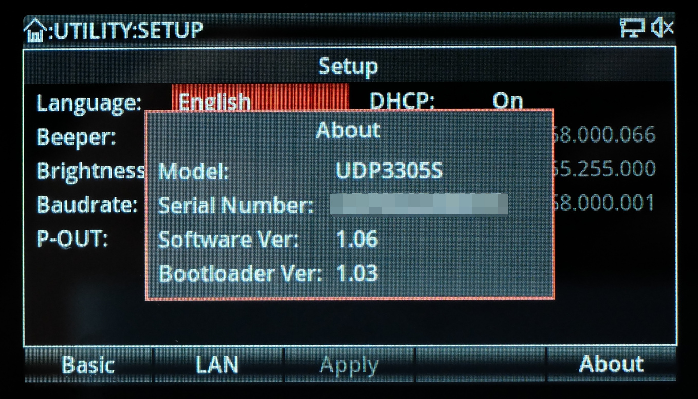
Unfortunately, I could not find a firmware update function in the user interface or the manual. And there are no firmware files on the UNI-T web site for the instrument. That's a pitty because I think getting firmware updates for a $600 power supply isn't asking too much.
Update 2023-06-25: I had contacted UNI-T support with some questions, one of which was about firmware updates. For quite some time I hadn't heard back from them so I gave it another try and it turned out that their reply had been rejected by my email provider's servers for some reason. So a support agent went through the trouble of tracking me down on LinkedIn. A+ for the effort! So I eventually got a reply but at first it was a bit sobering: The current firmware is v1.10 but I would have to send my instrument back to the factory for an update. But I didn't give up, immediately and we got into a constructive conversation – with a great result:
I got a current firmware image (v1.10) along with instructions to perform the update:
- Unpack the
*.rarfile to get the firmware imageUDP3305S.bin. - Put the image into the root folder of a FAT32 formatted usb thumb drive. Do not change the filename.
- Turn off the power supply.
- Insert the usb drive into the usb port on the back of the power supply.
- Press and hold the UTILITY button and turn on the instrument.
- Now the update process starts.
- Once the update has finished turn the supply off and on again.
- Done.
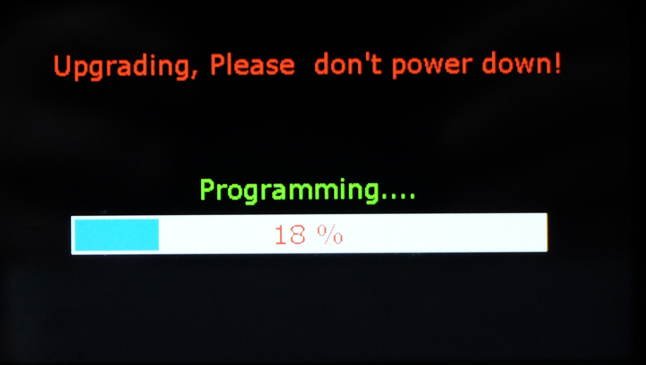
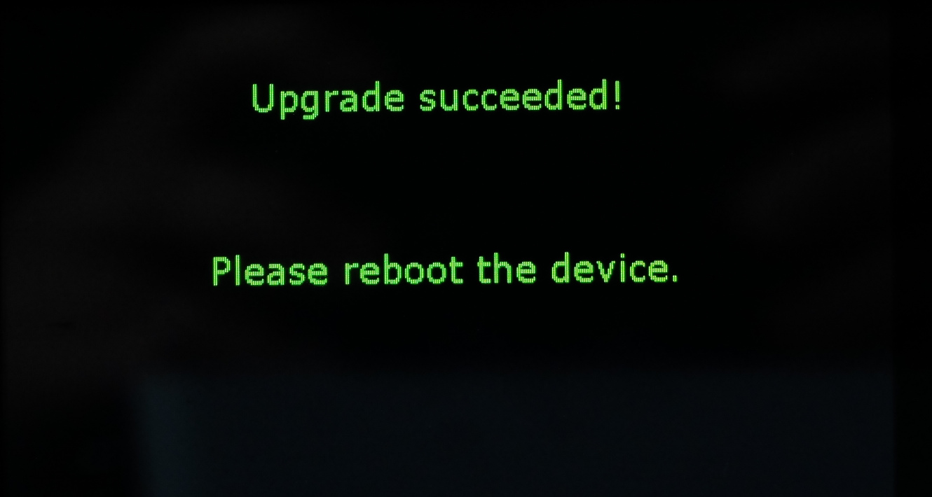
That worked like a charm:
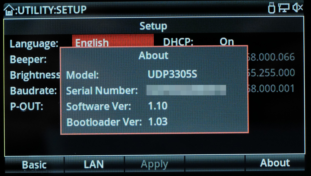
Excellent! I did let the support people know that I am very happy with this and I would be even more excited if this information and firmware files were available from their web site. According to their reply, UNI-T is planning to act on this some time in August. Wouldn't that be cool?
Measurement setup
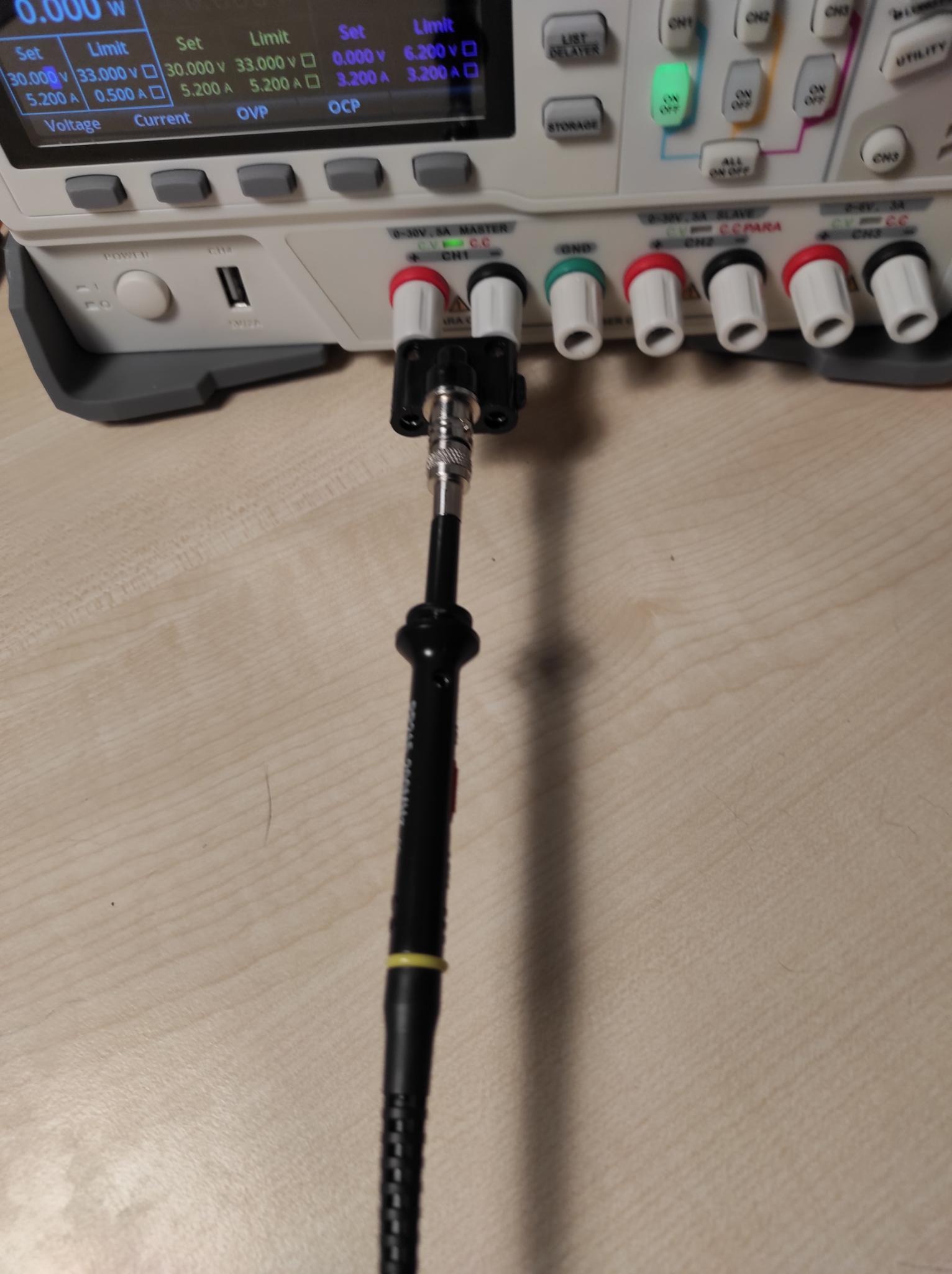
Below, I will use an electronic load so that I can test the device at different currents rather than just look at open-circuit voltages. My electronic load (East Tester ET5410+) is rather inexpensive but seems to do the job. It is important to correctly wire up the setup so that we measure voltages as close to the power supply as possible. At higher currents, there will be a noticeable voltage drop – even when using high quality cables. So:
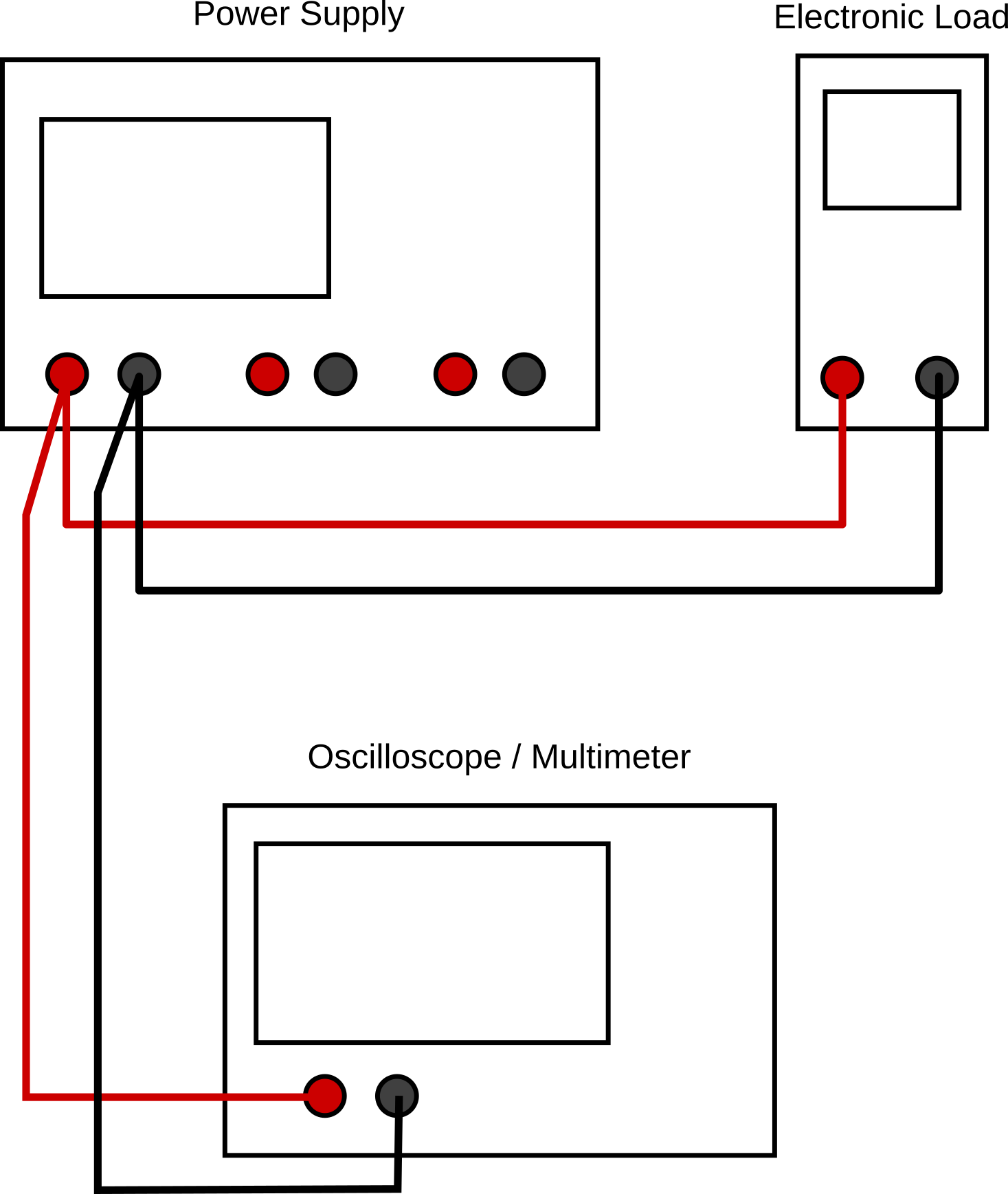
When connecting the oscilloscope, we use a proper probe with a BNC adapter and a BNC to banana plug adapter rather than simple leads in order to minimize problems with signals flying around the room.
Transformer taps
In order to prevent wasting too much energy in the voltage regulator, lab power supplies have multiple taps at different voltages and choose an appropriate one depending on the set output voltage. So let's try and find out how many there are and at which voltages. For that, I started at 0V and slowly cranked up the voltage until I could hear the telltale click of a relay.
- Channels 1 & 2 switch taps at about 5V, 11V, 17.5V and 25V
- Channel 3 apparently uses only one tap.
The exact switching voltages differ depending on where you are coming from. If you are increasing the voltage, the switch will be at a slightly different point than when turning down the voltage (hysteresis). And that makes a lot of sense because you don't want to get your power supply in a situation where it keeps switching just because you are operating close to a tap voltage.
On/Off behaviour
First, we'll check if there is any voltage present at the sockets when the channels are switched off. The above mentioned thread on EEVblog forum says there are small negative voltages present. Let's check:
- Channel 1: -11mV
- Channel 2: -243mV
- Channel 3: 0mV
That is exactly what was reported in the forum. Apparently, UNI-T has very consistent manufacturing. ;-)
Apparently, it's not unusual to see something like that in power supplies. I don't understand why but will not make a fuzz about it.
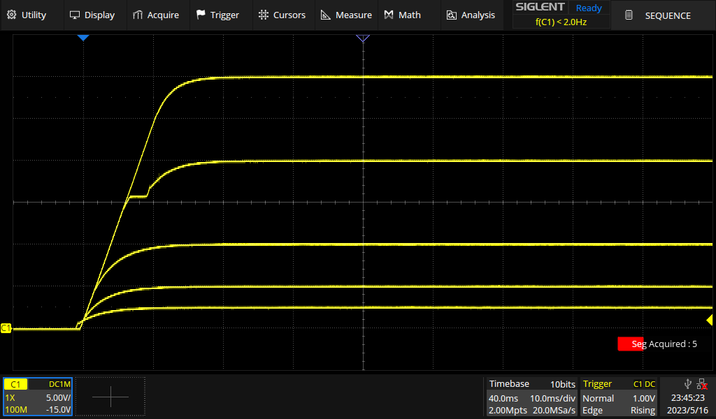
Next, we'll check what happens when a channel is turned on. So we'll set a few different voltages (2.5, 5, 10,20 and 30V for Ch1 & Ch2 and 2, 4, 6V for Ch 3) and record the voltage trace without any load connected:

And again with a load of 3A (Ch1/2) or 2A (Ch3):
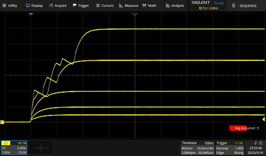
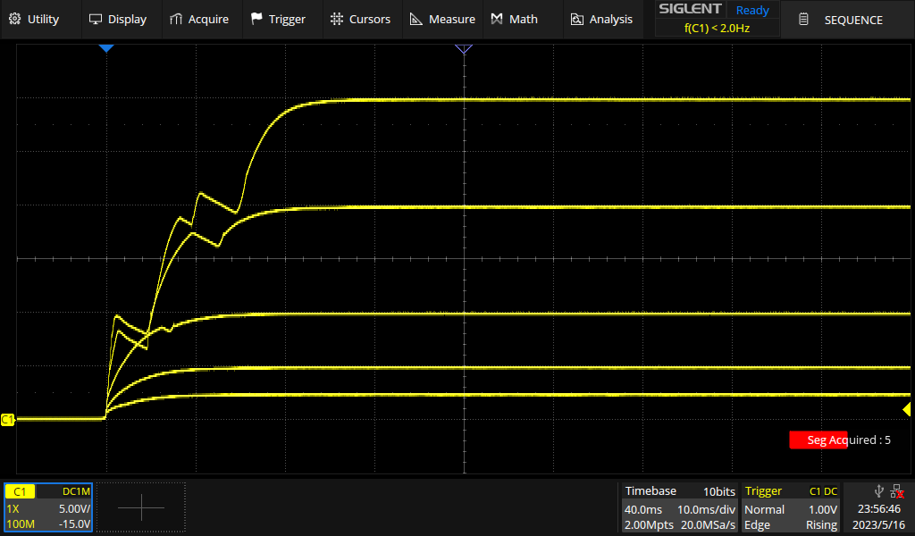
I see no overshoot in channels 1 and 2 while there is a little bit of it on channel 3 at lower voltages. Channels 1 and 2 also show some struggling to get to the target voltage in some cases. I have no idea what is going on there. However, I don't know if that is the power supply's fault or if the electronic load has a part in it. So I'll repeat the experiment using a power resistor (12Ω, 100W) instead of the electronic load.
Ch1 & Ch2:
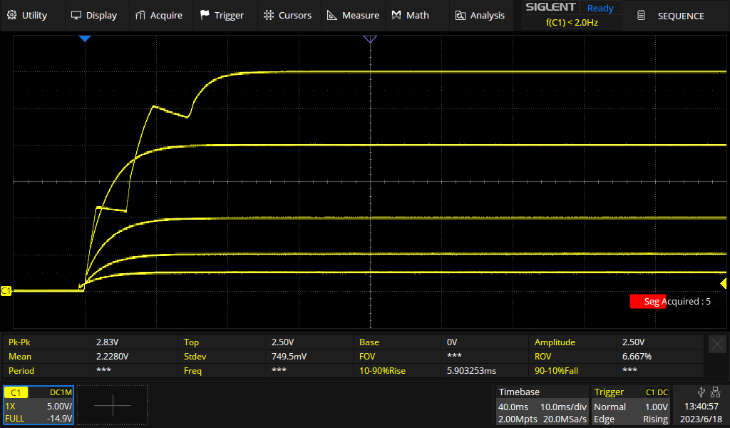
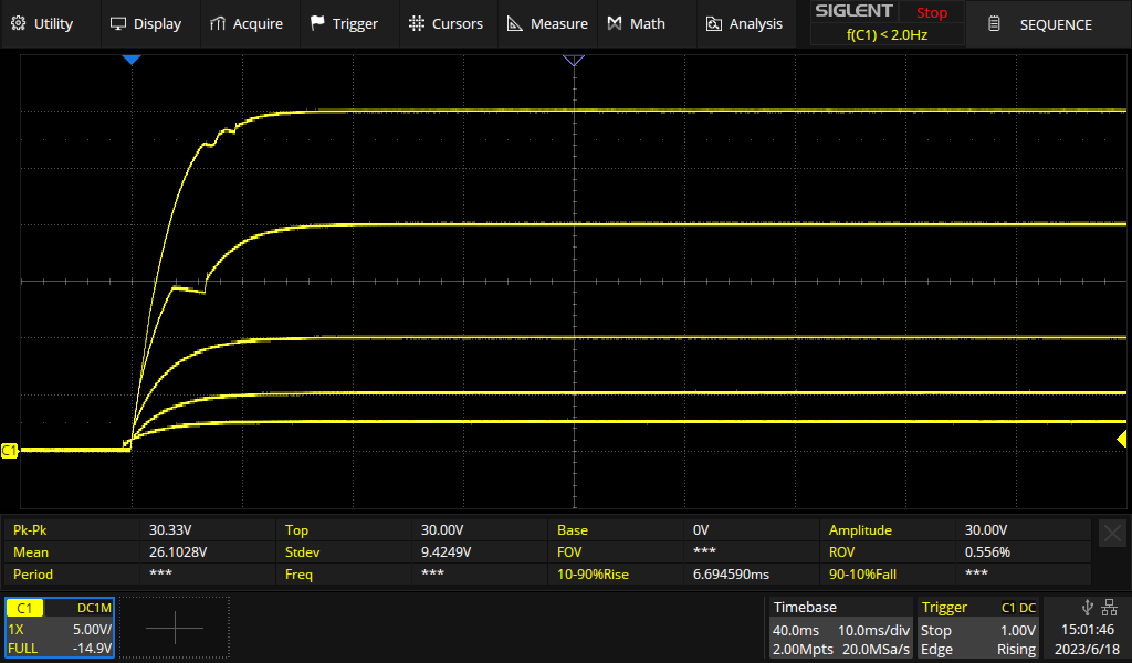
Ch3:

Better, but still not completely smooth.
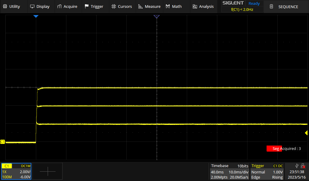
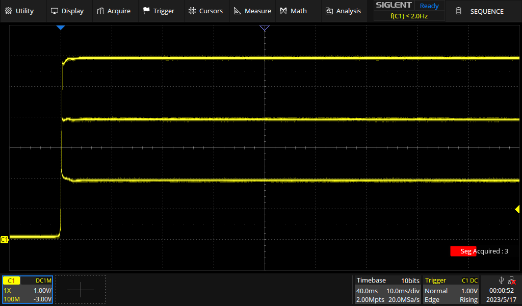
After studying the on behaviour, let's have a quick look at the trace when turning off a channel (30V @3A for Ch1&2; 6V @2A for Ch3:

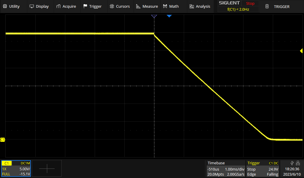
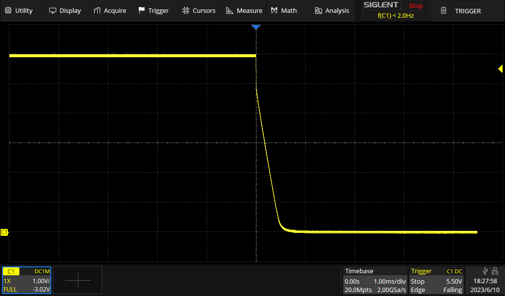
As expected, that looks pretty boring. Essentially, we are watching a capacitor discharging.
Finally, there is a button labeled all on/off that turns all three channels on or off, respectively. But what happens, if some channels are on while others are off? The PSU does the right thing and will turn all channels off in that situation. That is important, because turning everything on, instead may put connected circuits in danger when you need to turn off everything quickly – e.g. in order to prevent damage.
Load change
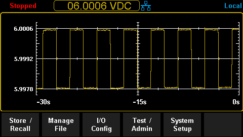
Next, we'll test how well the supply can handle changing loads. I programmed the electronic load to alternate between 1A and 4.5A every 2 seconds (transient mode). The supply is set to 30V. I didn't really see much on the oscilloscope so I switched to the best multimeter I have (Siglent SDM3065X; aperture 0.5 PLC).
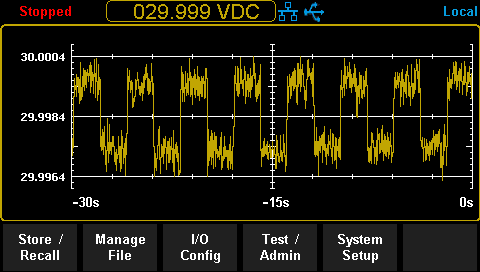
That looks really good to me. The supply manages to keep the voltage remarkably stable.
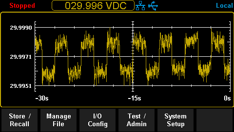
So repeat that for channel 3(6V, 250mA/2.5A):
Again – no complaints.
Constant current mode
Good power supplies have a current limiting mode so that you can set a maximum current and the device will quickly lower the output voltage when the limit is exceeded until we are back at the current limit. That way, we can protect our circuit from over current damage in case it is faulty and tries to draw too much power. The faster our power supply manages to get back to normal, the better.
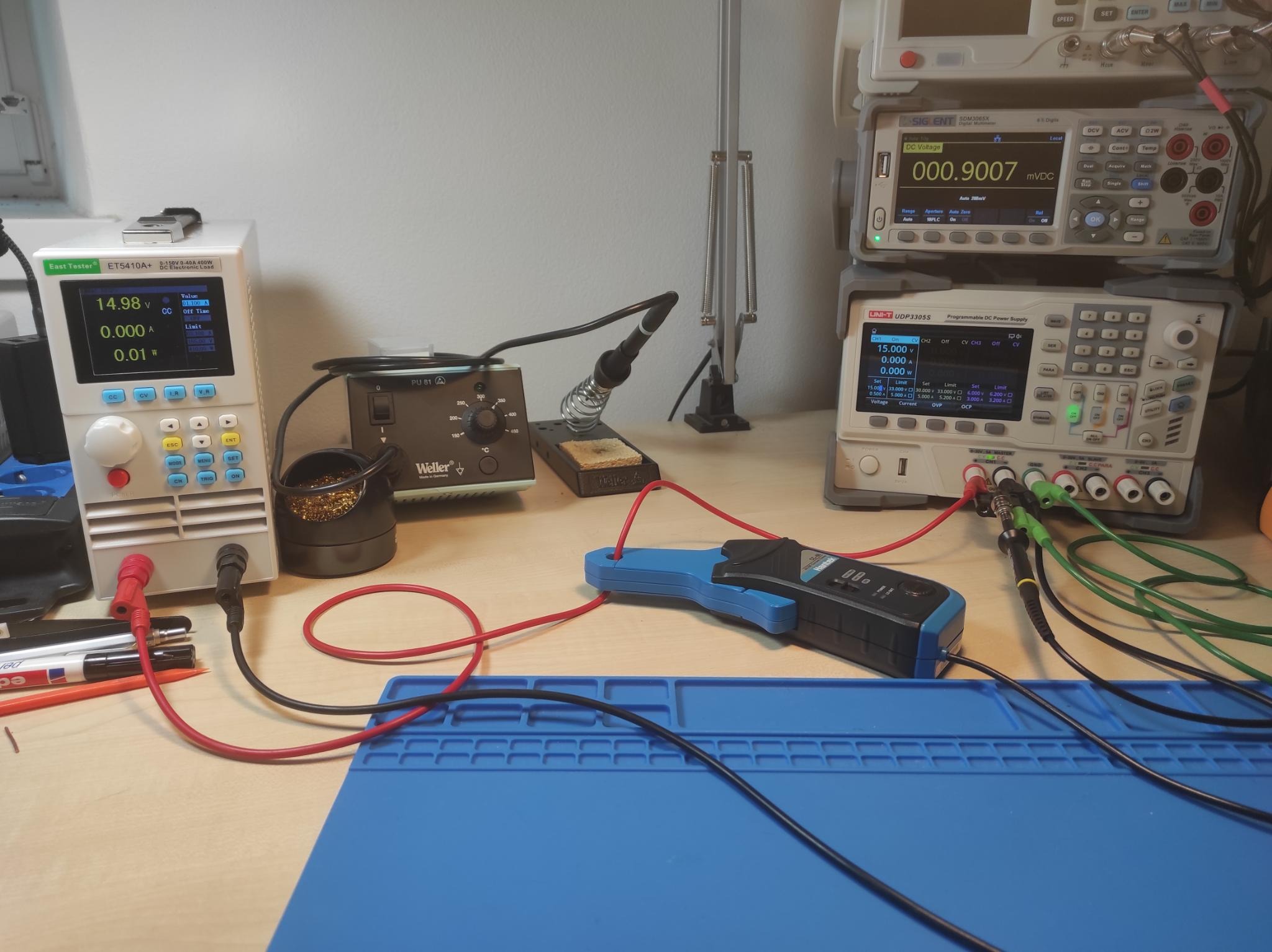
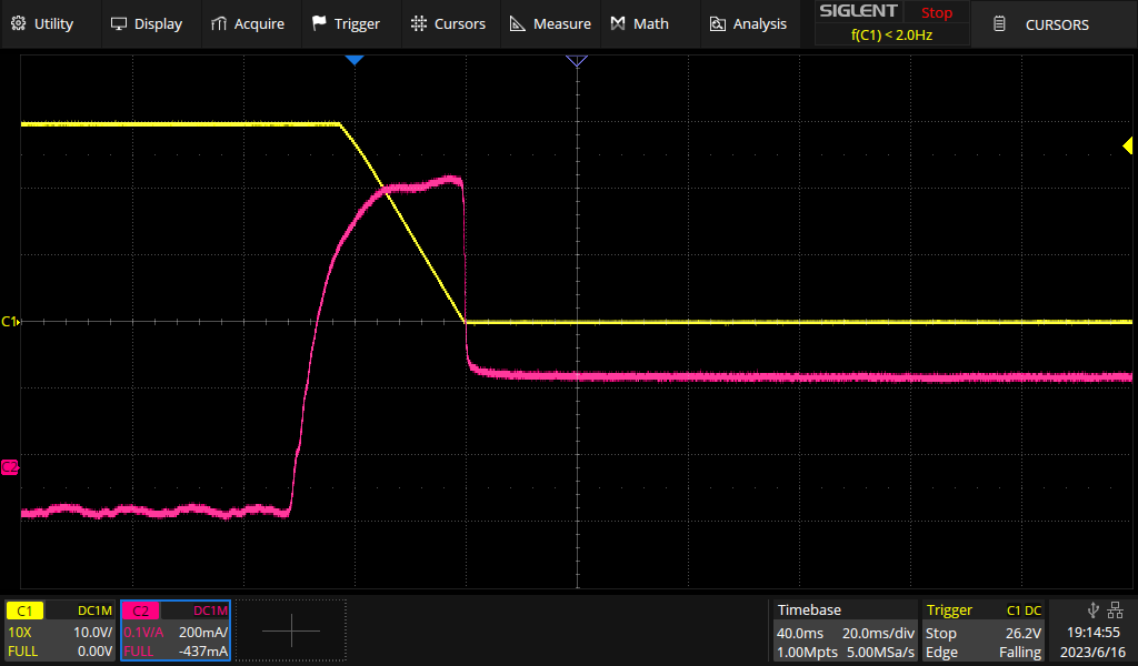
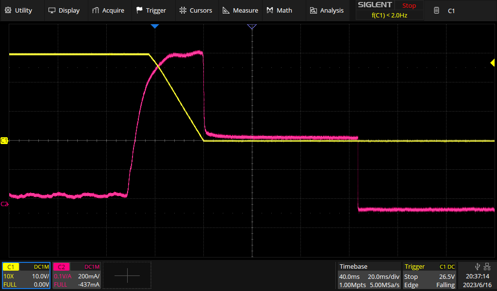
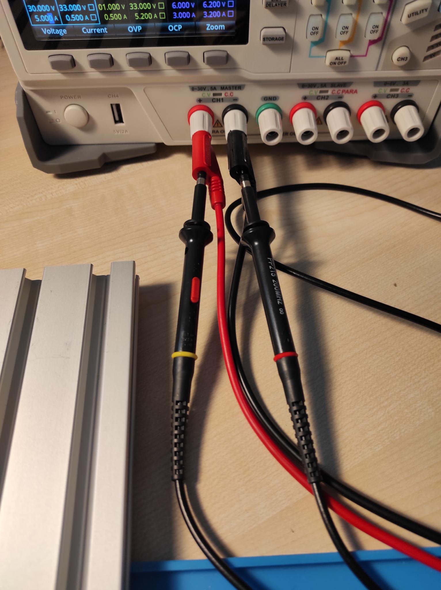
For testing this feature, I set the current limit to a certain value and ran it at a low current (load 1) before suddenly increasing the load above the current limit (load 2). On the oscilloscope, we observe the voltage (Ch1, yellow) and the current (Ch2, magenta, via a Hantek CC-65 current probe).
This is what our setup looks like:
We are using these parameters:
| Channel | U [V] | I Limit [A] | Load 1 [A] | Load 2 [A] |
|---|---|---|---|---|
| 1 & 2 | 30 | 0.500 | 0.100 | 1.1A |
| 1 & 2 | 15 | 0.500 | 0.100 | 1.1A |
| 3 | 6 | 0.500 | 0.100 | 1.1A |
And here comes Channel 1:
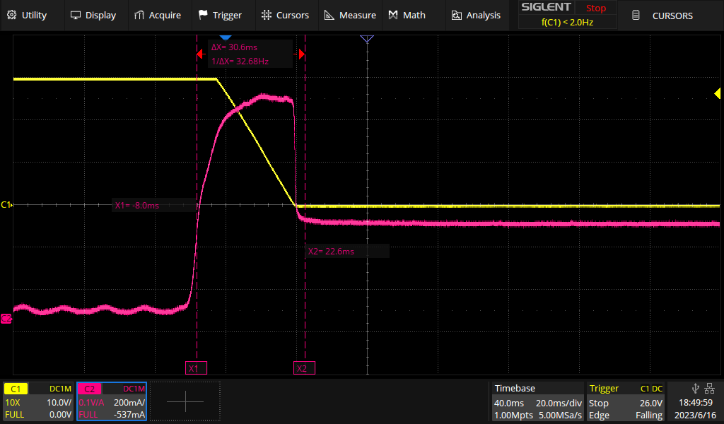
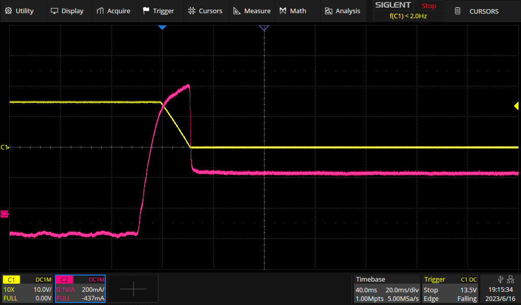
Channel 2:
And Channel 3:
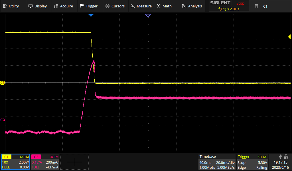
So at 30V, it took about 30ms between crossing the current limit and getting back to that level after an overshoot of up to about 1A. At 15V, at took ≈20ms. Channel 3 is faster, yet at 6V.
While I really like looking at such plots, we will top it all off with a trivial, yet relevant experiment: We will torture a red LED.
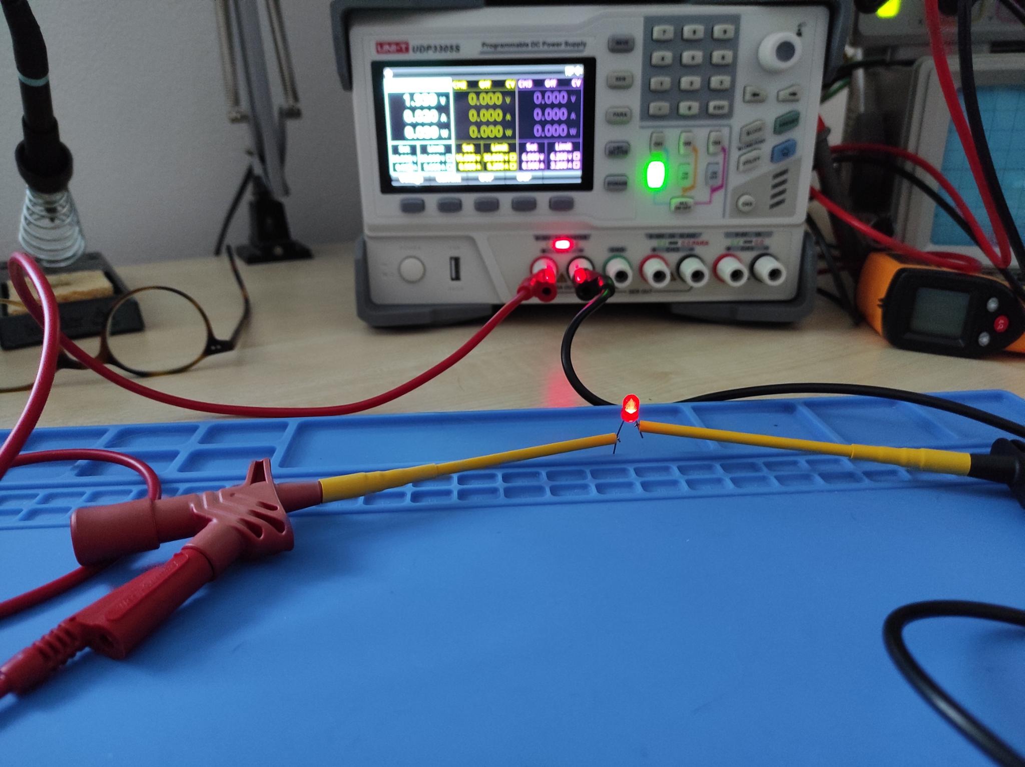
We'll connect it to the supply w/o a series resistor and test it, first. At 20mA it glows nice and bright.
Now we set the current limiter to 20mA and the voltage to full throttle (30V). Turn on the channel and see what happens. The power supply immediately goes into CC mode and the LED glows nicely at 1.9V, 20mA.
Now let's stress test it: Turn if off again, and on and off, and ... until the LED dies or I don't feel like trying any longer. After 100 cycles I gave up and the LED looked unharmed.
Over current protection
In addition to current limiting, the device has an over current protection mode in which it will inactivate the channel after the maximum current was exceeded. To test it, we will use the same setup as above and set both limits to 500mA.
And here is what happens:

First, we see the same current limiting response as above. But about 90ms after the current reached the limit, the channel is turned off entirely.
I'll skip testing Ch2 and Ch3 on this one.
Setting and readback accuracy
In this section, we will explore how closely the voltage and current that we set corresponds to the actual output. We will also test the accuracy of the values that the power supply reports back to us.
The data sheet says:
Programming accuracy
Voltage: ±(0.03%+10mV)
Current: ±(0.2%+5mA)
Readback accuracy
Voltage: ±(0.03%+10mV)
Current: ±(0.15%+5mA)
Voltage
For this experiment, we will set various different voltages and loads (ET5410A+) without a current limit. I am using a new Siglent SDM3065X multimeter to measure the actual output. As this is a pretty precise measurement, I turned on all instruments involved and allowed them to sit and equilibrate for about an hour at 22.2 °C (Fluke 87V with a k-type probe).
Here comes my protocol:
- Channel 1 & 2:
- Voltage: 1 - 30V in 1V steps
- Current limit: 5.2A
- Electronic load: 0, 1, 2.5, 5A
- Channel 3:
- Voltage: 1 - 6V in 1V steps
- Current limit: 3.2A
- Electronic load: 0, 0.25, 1.5, 3A
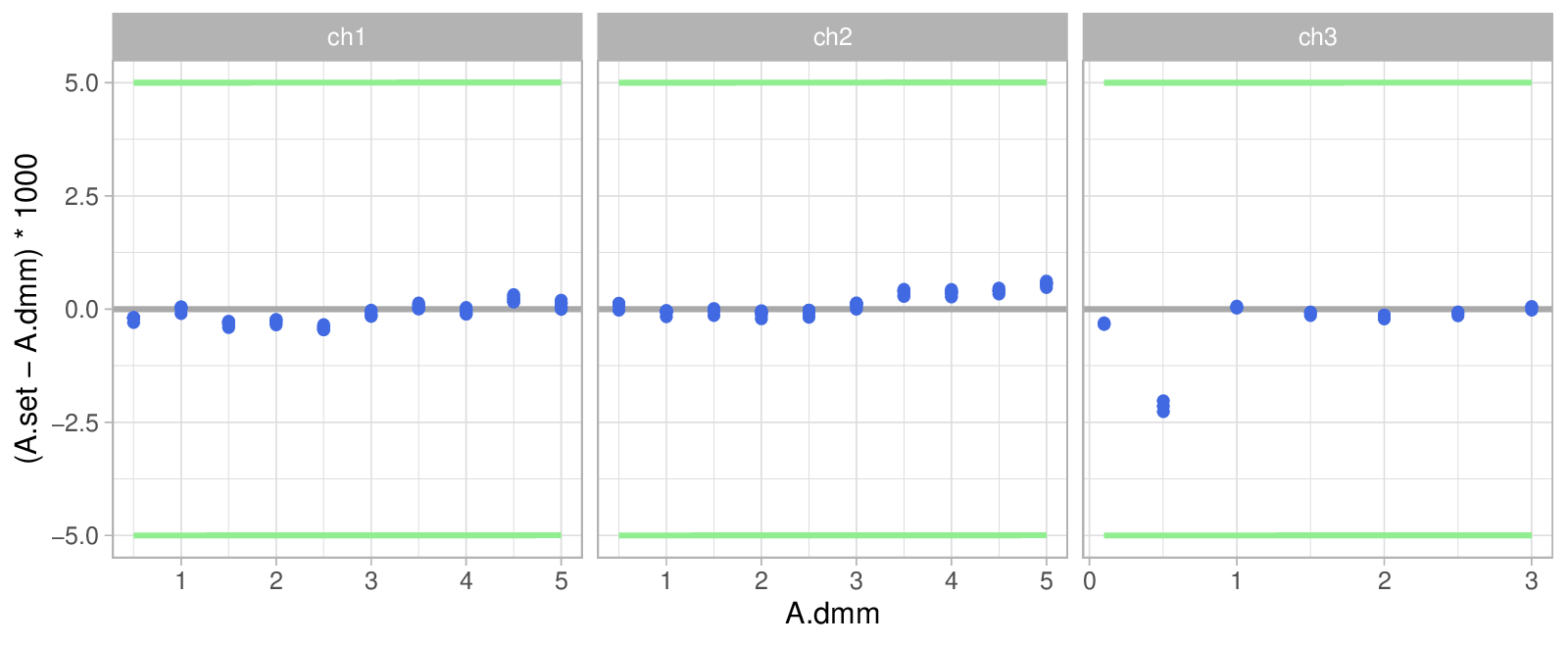
Now, we plot the deviation (in mV) of the set/readback voltages (V.set /
V.psu) against the measured voltage (V.dmm). The green lines represent the
specification limits and the dots are color coded by the current reported by
the PSU (A.psu)
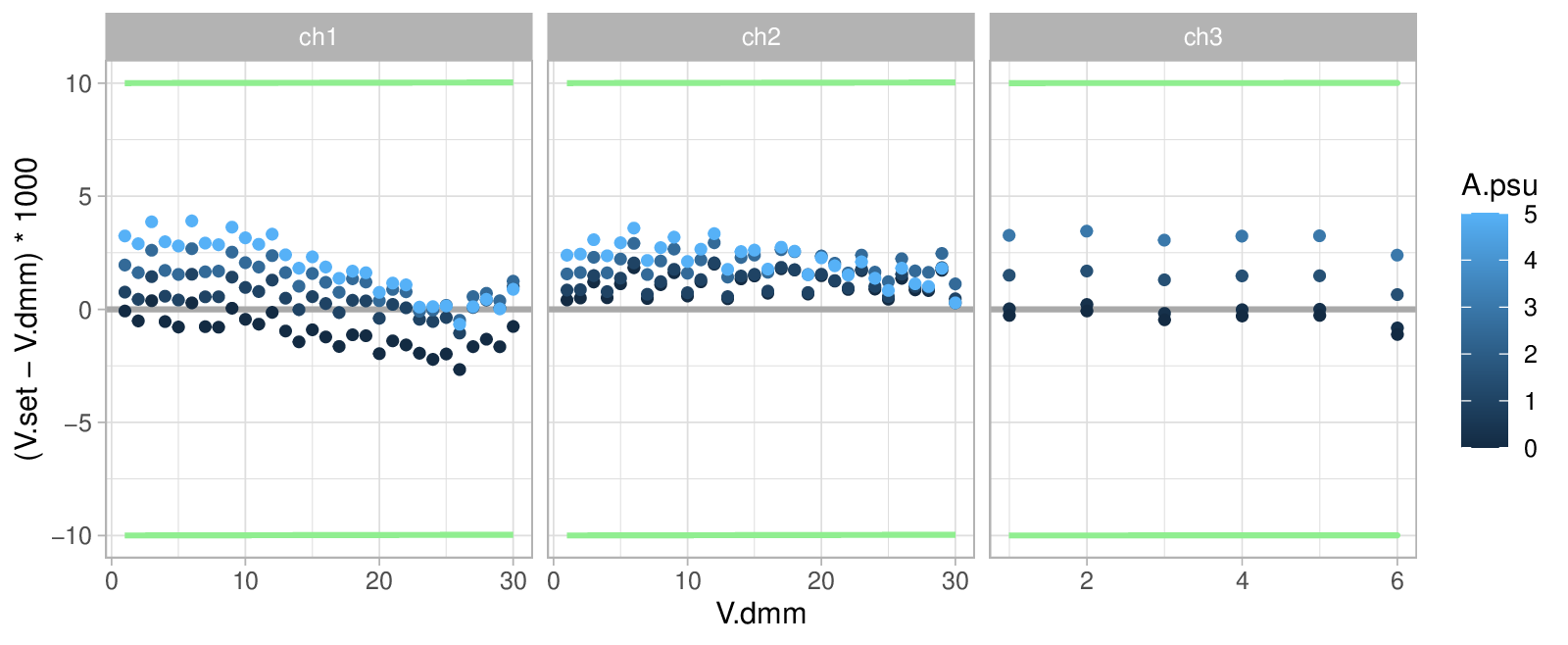
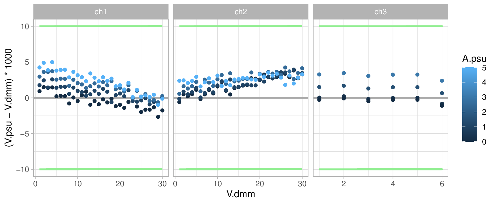
Great – all data points are well within spec.
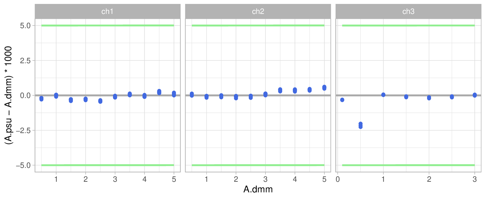
And out of curiosity, we also have a look at how much V.set and V.psu differ
in our little data set:
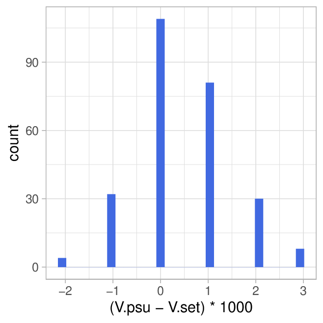
Marginally.
Current
In order to analyze current accuracy, we will take measurements at various voltage/current settings while setting the electronic load to 6A so that it will always try to consume more power than the limit allows, thus putting the PSU into cc mode.
- Channel 1 & 2:
- Voltage: 5, 10, 20, 30v
- Current: 0.5, 1, 2.5, 5A
- Electronic load: 6A
- Channel 3:
- Voltage 2, 4, 6V
- Current: 0.5, 1, 2, 3A
- Electronic load: 6A
And this is what the data looks like:
Everything is well within the specified limits. There seems to be a weird outlier behaviour for Ch 3 at 500mA – no idea what may cause that. But although strange its in spec.
Ripple & Noise
Good power supplies deliver very "clean" voltage and current – i.e. there is very little AC on the DC. Linear PSUs are typically pretty good while switch mode supplies often struggle in this department.
The term Ripple refers to the periodic AC signal that originates from the 50/60Hz line frequency (or the internal switching frequency in case of a switching supply). Noise is all the remaining junk that comes on top of it.
So measuring that sounds easy enough – just connect some wires to the PSU and connect them to your oscilloscope. In reality, this is a pretty tricky measurement to get right, because your leads or even scope probes will happily act as antennas and ruin your measurement. Dave Jones has a pretty good video on the topic.
The data sheet says: : "<350μVrms/2mVpp(5Hz~1MHz)". That is a bit unusual, as these values are typically given at <20MHz – but well.
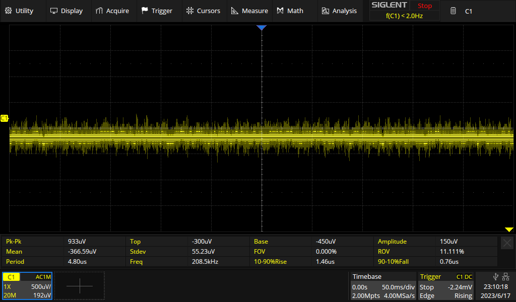
So let's try and take some measurements. Crank the sensitivity all the way up – on my scope that means 500µV/div. Without connecting to anything but the bare probe I get this:
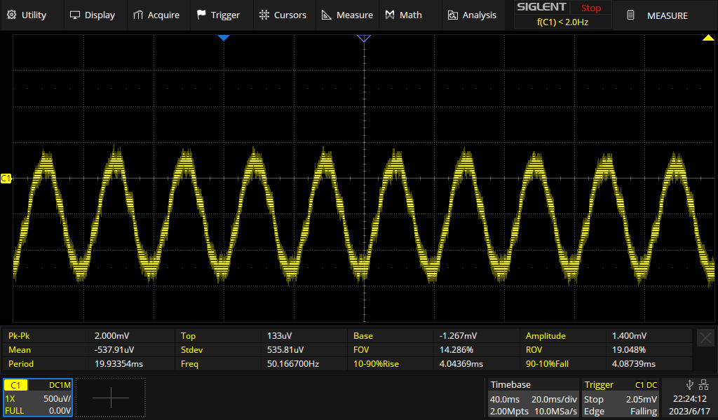
Not good. Apparently my probe is enough of an antenna to pick up quite some ripple and noise out of thin air. And, of course, the scope itself also has some noise. All in all we already have 2mVpp which is the spec limit of the PSU... So I connected a BNC-adapter to the probe and plugged that into a BNC to Banana adapter which is then plugged into the scope. If we are lucky, that has enough shielding to get rid of most of the crap.
Now we set the scope to AC coupling and turn on the bandwidth limiter (20MHz).
That worked surprisingly well:
Ch1 & Ch1:
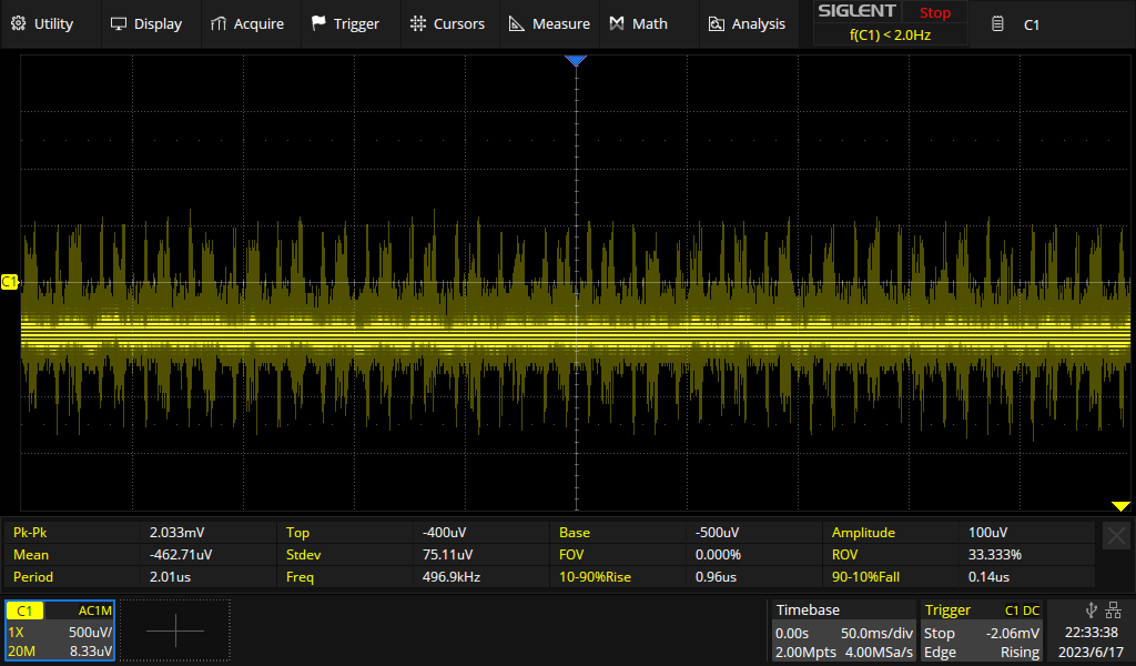
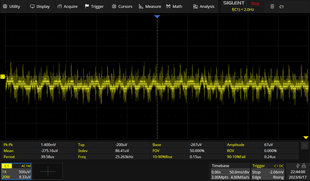
Ch3:
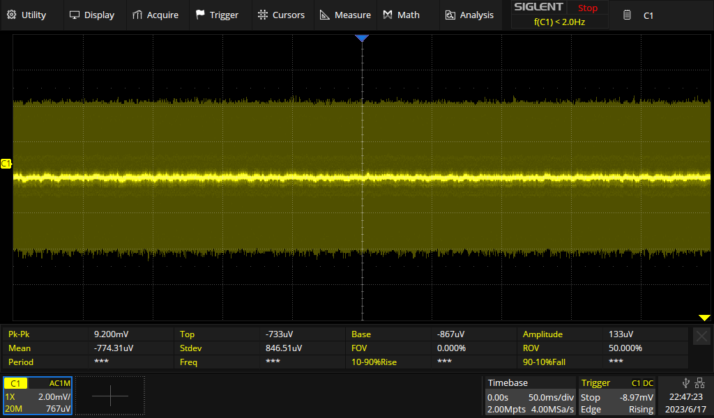
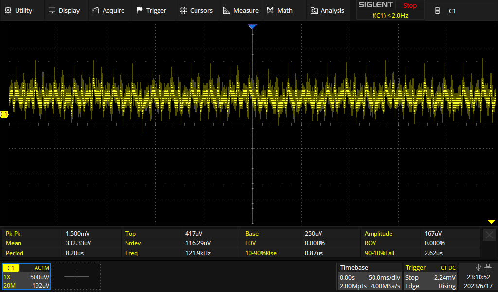
And again, this time with 1A load on it:
Ch1 & Ch1:
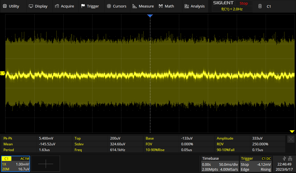
Ch3 (I had to lower the sensitivity to capture all of it, here):
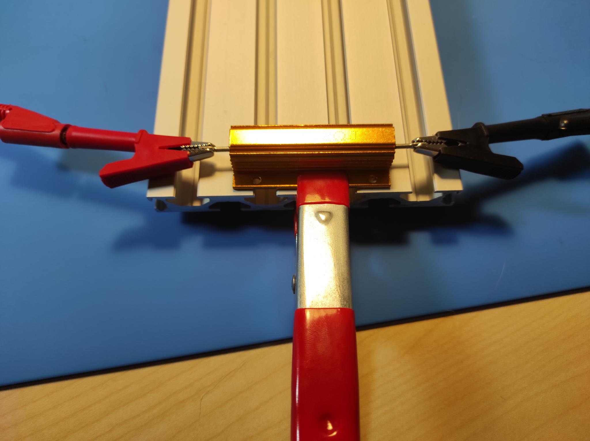
Wow – quite a bit noisier than before. But maybe that is due to the electronic load? To sort that out, we'll try again – with a load resistor (12Ω, 100W). But first let's do some math so we don't blow up the resistor:
30V / 12 Ω = 2.5A
30V ∙ 2.5A = 75W
Ok – that's fine. I clamped the resistor to a bit of aluminum extrusion as a heat sink, but it still gets really hot in seconds.
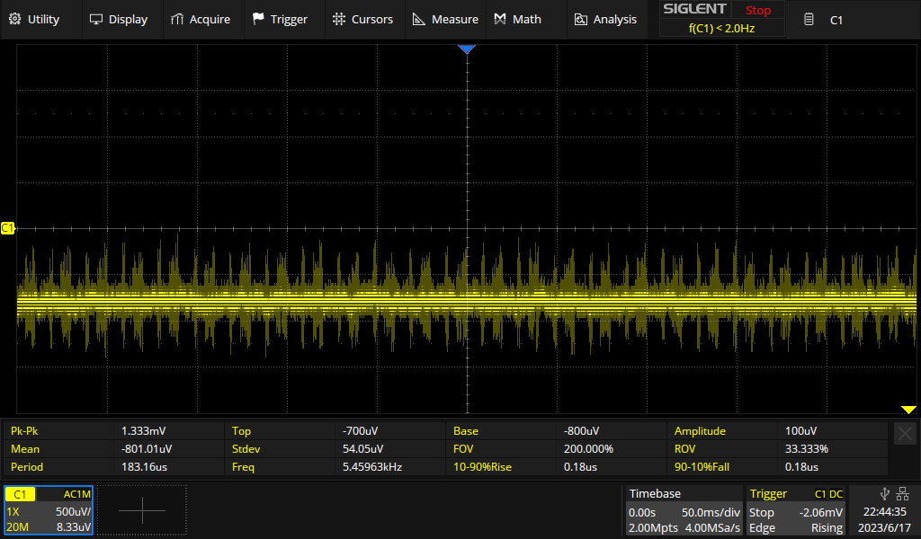
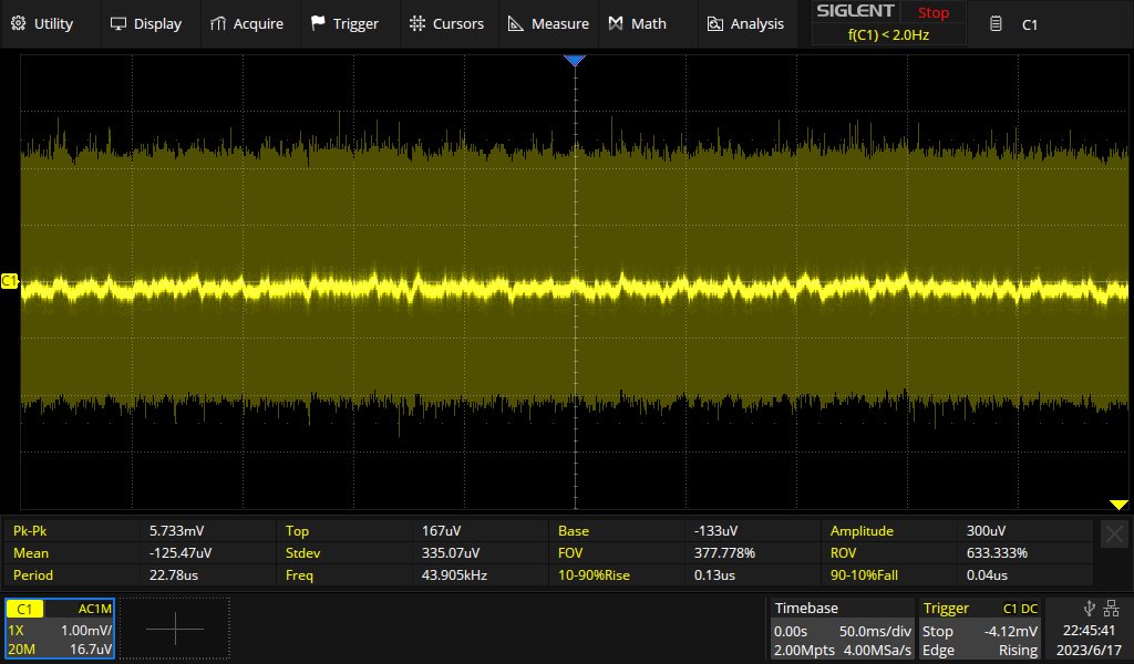
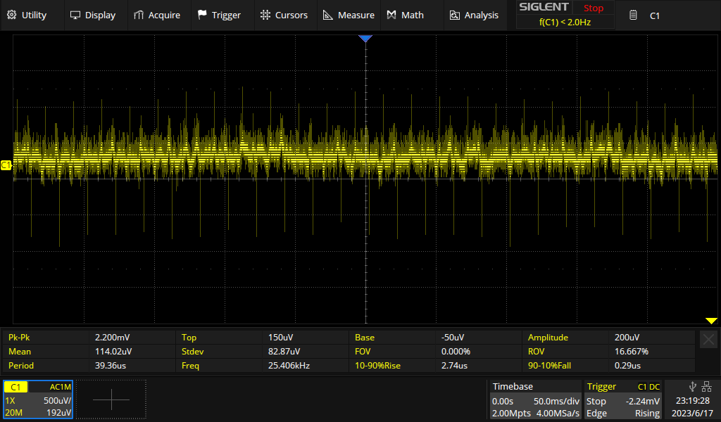
Here comes the result:
Ch1 & Ch1:
Ch3:
Not bad at all! Overall we get somewhere between 1 and 2.2mV peak-to-peak. Given that the scope and probe contribute to the noise, I would say the PSU is in spec.
Finally, I tried to crank up my technique a bit and do a differential measurement using two scope probes – one connected to the positive and the other to the negative terminal of the supply. In theory, I can then subtract the channels to get a good ripple&noise signal without the common mode stuff. However, I couldn't make that work. The difference line was always a perfect zero line.
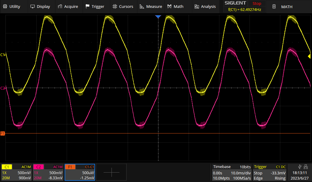
At the settings above, ripple&noise are drowning in the huge signals. Note the factor 1000 difference in sensitivity between Ch1/Ch2 and the difference trace. The probes just receive too much crap out of thin air and the adc simply doesn't resolve the noise at these settings. Increasing sensitivity on the channels doesn't help either, because then they go off the screen (clipping) and there is nothing left for the math function to work with. Maybe I can bodge together some kind of shielding, later.
So at this point I give up and admit that I am not sufficiently equipped (or knowledgable) to really quantify ripple & noise of the supply any better. I guess I'd need a really low noise differential amplifier...
Verdict
The power supply is easy to operate and has many useful features. All aspects of performance that I tested look really good. The PSU is easy to program via buttons and menus and remote control via SCPI was easy to set up. I was going to complain about the lack of firmware updates but as I said above that has been fixed. It would be nice if a future firmware update added tracking mode to the feature list. And compared to the Rigol DP832A, the manual of the UNI-T device is not that great but I managed to figure everything out without much problems.
Overall I am very happy with the power supply and would buy it again.
Update 2023-11-14
It took a while, but now UNI-T are providing the firmware for download on their homepage.
Update 2024-04-23
VoltLog hs published a very similar review of the PSU on Youtube. He also added a Teardown video briefly after that. He does touch a few thing I did not include so it's worth watching.